#16 · 128x64 ST7920 graphical/dot-matrix SPI LCD
Tutorial goals
- Working with the U8g2 library
Components needed
- 1× Arduino
- 1× Breadboard
- 1× Grafisch/dot-matrix SPI 128x64 LCD
- 10× Jumper wire (male-male)
Buy components
- $ 7.35 Arduino Uno (clone) with cable
- $ 12.77 Arduino Uno (clone)
- $ 25.97 Arduino Uno SMD (original)
- $ 27.31 Arduino Uno Chip (original)
- $ 1.90 1x breadboard small
- $ 2.11 1x breadboard small
- $ 0.52 1x breadboard large
- $ 3.39 1x breadboard large
- $ 0.52 Jumper wire assortment (MM/MF/FF)
- $ 0.52 Jumper wire male-male
- $ 3.27 Jumper wire male-male
- $ 6.74 ST7920 128x64 Dots Graphic LCD
- $ 13.32 ST7920 128x64 Dots Graphic LCD
All products shown are not being sold by Bas on Tech.
Introduction
How cool is it to display information on a screen? In tutorial 11 we already looked at an I2C LCD character display . Let's take it a step further with a larger dot-matrix display .
In this lesson you'll learn how to display the demo code of the [U8g2 library] (https://github.com/olikraus/u8g2) on your screen.
Course material
At the bottom of this page you'll find the course material button. This button allows you to download the code, circuit diagram and other files relevant to this Arduino tutorial.
ST7920 LCD dot-matrix display

The ST7920 is a so-called LCD which stands for Liquid Crystal Display. This screen is made up of segments that can be turned on or off. These segments are placed as an '8' in some screens like a digital clock, in others as pixels.
With LCD it looks like the boxes can become black. Technically this is not true. The light is transmitted differently making it appear black. More details on Wikipedia
ST7920 refers to the display controller which is made by Taiwanese Sitronix.
De specs of the ST7920 LCD
| Type | LCD |
| Format | 128x64 pixels |
| Screen diagonal | 2.9 inch |
| Dimensions | 93x70mm |
| Power supply | 2.7 to 5.5V |
| Color | blue/white or green/black |
More technical information is described in the ST7920 datasheet
U8g2 library
The U8g2 library is specially made to easily control monochrome displays in an universal way. U8g2 allows you to draw graphic elements such as lines, rectangles, circles on the screen. Text is also no problem.
An overview of all available functions can be found on the U8g2 reference page. Currently U8g2 supports over 200 different displays. The big advantage is that you don't have to find out how to control each individual display.
Printing the ST7920 pin overlay
In this circuit we use a breadboard . If you put the display into the breadboard you'll see that the pin labels are no longer visible. To solve this I've created a pin overlay. Print this PDF and cut out the overlay. You can now place this exactly at the bottom of your display and see the pin labels again.
If the pin overlay does not not fit exactly, check your printer settings to see if the magnification is set to 100%.

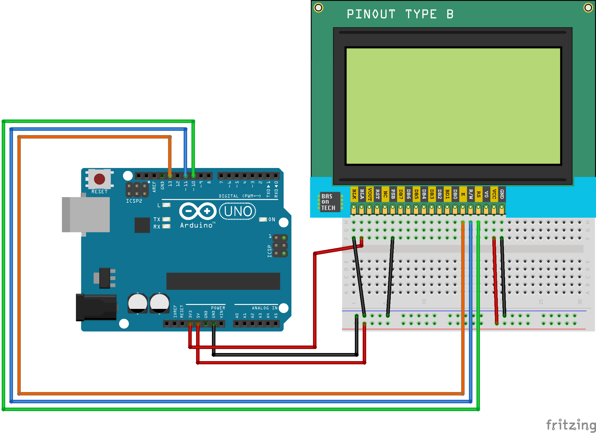
The circuit
Step 1 - breadboard
We start by supplying the breadboard with 5V on the + rail (red) and GND on the - rail (blue). For this we connect the '5V' on the :KnSgtg:Arduino:: to the breadboard. We do the same for the GND.

Step 2 - powering the LCD
The next step is to provide 5V to the LCD. To do this, we use the 'Vcc' and 'GND' pins on the far right of the display. Connect these to the + rail and - rail on the breadboard.

Step 3 - LCD backlight (optional)
Then it is time to connect the backlight. This is an LED backlight with an anode (+) and cathode (-). The backlight LEDs work on 3.3V, so DO NOT connect it to the 5V because then you can damage the backlight.
We connect the 3V3 on the Arduino to the BLA (Backlight Anode), and the BLK (BackLight Cathode) to the - rail on the breadboard.

Step 4 - Serial data
Now we have to tell the display how we are going to provide the data. We are going to use the SPI (Serial Peripheral Interface) protocol. The name already reaveals it a bit, the data is serial. With the PSB pin we can set the data transfer mode.
If we make the PSB pin high, the display expects parallel data, with LOW serial. In our case we have to make the PSB pin LOW by connecting it to the - rail.

Step 5 - SPI
The last step is to connect the data lines for the SPI communication. SPI uses three different lines:
- Serial Clock
SCK - Master In Slave Out
MOSI - Chip Select
CS
We will use 'Pin 13' on the Arduino (orange line) as serial clock 'SCK'. On the display it is labeled as pin E.
For the Master In Slave Out MOSI of the SPI protocol we connect Arduino pin 11 (blue line) to the RW pin (read / write) on the display.
The last step is to connect the CS (chip select) wire. On the display it is labeled RS which stands for Register Select and it will be connected to pin 10 on the Arduino.

The circuit is now completely finished! Time to code! 😎
Arduino Code
As indicated earlier, we use the U8g2 library. We will first install this via:
Search for U8g2 and press install for the U8g2 by Oliver library
We are going to use U8g2's demo code.
If you scroll down a bit you will see a lot of definitions of displays that resemble:
1 //U8G2_ST7920_128X64_1_8080 u8g2(U8G2_R0, 8, 9, 10, 11, 4, 5, 6, 7, /*enable=*/ 18 /* A4 */, /*cs=*/ U8X8_PIN_NONE, /*dc/rs=*/ 17 /* A3 */, /*reset=*/ 15 /* A1 */);
2 //U8G2_ST7920_128X64_1_SW_SPI u8g2(U8G2_R0, /* clock=*/ 18 /* A4 */ , /* data=*/ 16 /* A2 */, /* CS=*/ 17 /* A3 */, /* reset=*/ U8X8_PIN_NONE);
3 //U8G2_ST7920_128X64_1_SW_SPI u8g2(U8G2_R0, /* clock=*/ 13, /* data=*/ 11, /* CS=*/ 10, /* reset=*/ 8);
4 //U8G2_ST7920_128X64_1_HW_SPI u8g2(U8G2_R0, /* CS=*/ 10, /* reset=*/ 8);
For our display this line is the one we're going to use
1 U8G2_ST7920_128X64_1_SW_SPI u8g2(U8G2_R0, /* clock=*/ 13, /* data=*/ 11, /* CS=*/ 10, /* reset=*/ 8);
Remove the // in front so it isn't commented. You can see exactly the Arduino pins to which we previously connected the data lines.
Uploading code to the Arduino
Now our program is ready to upload to the Arduino. First we have to connect our Arduino to the computer with the USB cable. Make sure you've selected the correct board in the IDE:
and the correct port:
If you are not sure which port to use, try them all until you can successfully upload your code.
The top left shows a round button with a checkmark. By pressing this button you tell the IDE to verify your code for possible errors. The IDE only checks if it can read your code. It does not check if you have written correct code for what you are trying to program.
If everything works the IDE shows the Compiling completed message. You can now upload your code by pressing the round button with the arrow to the right. The uploading is complete when the Avrdude done. Thank you. messages appears. Your program will immediately start after uploading.
U8g2 demo code on screen
The code should now work on your Arduino. If not, check that you have connected all wires properly and that no connections are loose.

Challenge 🚀
Another Arduino tutorial finished! Here is a challenge:
🎓 Look at the functions in the code and experiment by tweaking things. For example, see if you can give the shapes other sizes.
Good luck!